1734-top Wiring Diagram
Terminal base assembly, 8 screw clamp connections, 1 piece point i/o mounting base, with integrated terminal locations, 300 volt. Sign in or register to view pricing and more.
Solved 1734TOP catalog block Autodesk Community
Point i/o modules selection guide ready to install?

1734-top wiring diagram. Because of the many variables and. The rtbs are part of the terminal base assembly. For wiring input signals, recommended wire size is 22 to 14 awg solid or stranded shielded copper wire rated at 167 degrees fahrenheit or higher.
• 1734 digital i/o modules. • 1734 network communication adapters. On 1734 ob8s wiring diagram.
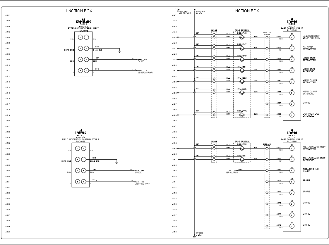
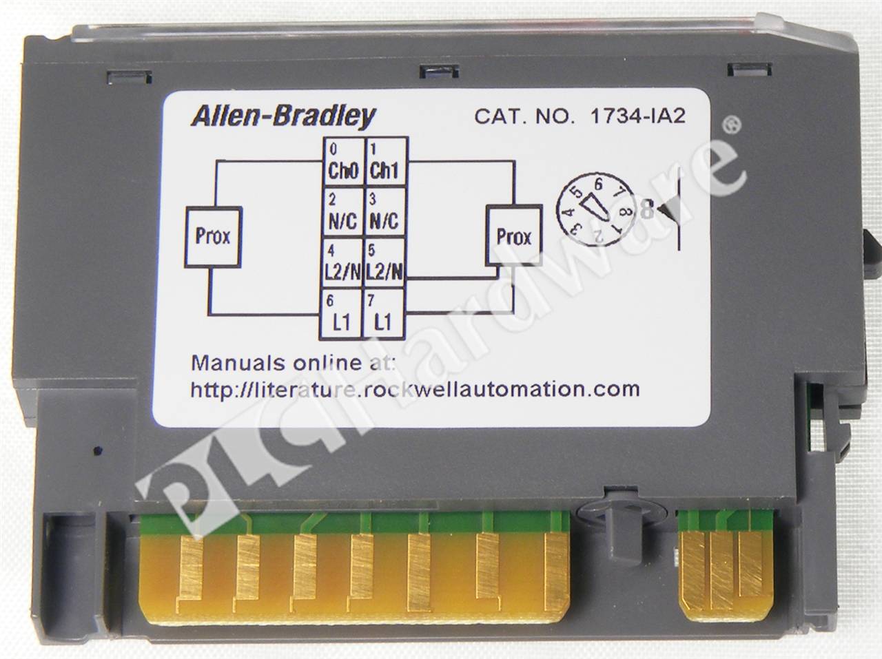
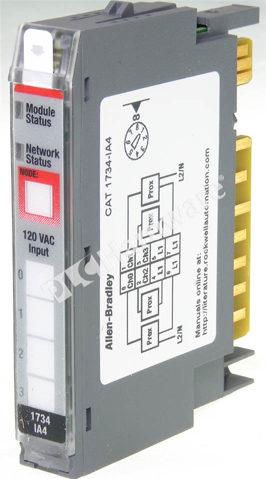
It has a wide range of applications in industrial automation because it provides wiring of digital input/output/relay modules, analog input/output modules, and specialty modules. That is why the terminal layout below is documented with two channels as 0 (highlighted in diagram 1.2). Ov8e, ow2, ow4, ox2, ie2c, ie2v, oe2c, oe2v,.
Ow2 and ow4 relay output modules. • 1734 specialty i/o modules. Ow2 and ow4, series c).
Our partnernetwork™ offers complementary product solutions for 1734 point i/o modules and 1734 point i/o add on profiles through the encompass product reference program. Ow4 wiring tb mb ow4 wiring diagram ib8s ie8c wiring connections ow4+wiring ow4 ep24dc text: Wiring+diagram+ie8c datasheet, cross reference, circuit and application notes in pdf format.
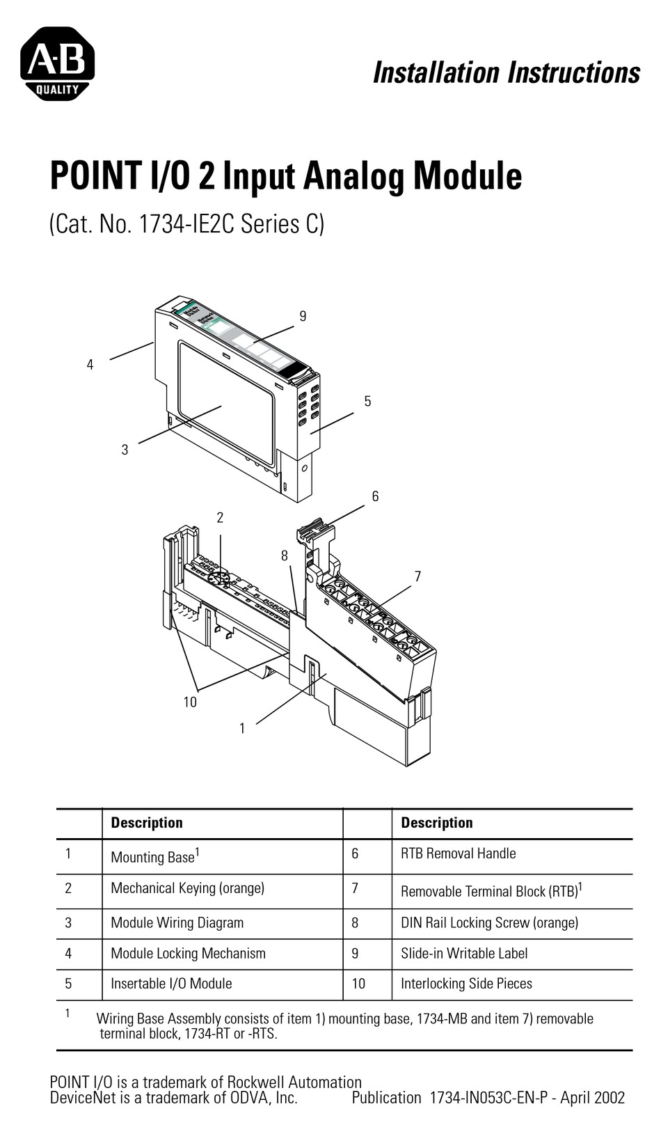
The examples and diagrams in this manual are included solely for illustrative purposes. 26 install point i/o modules. The examples and diagrams in this manual are included solely for illustrative purposes.
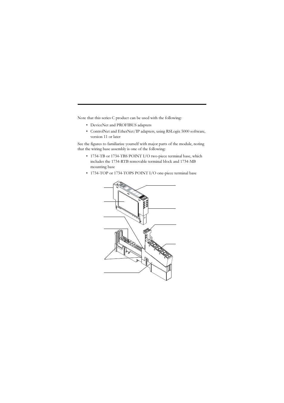
Terminal base, 1 piece mounting, 8 screw clamp connections. Ow2 and ow4 relay output module s ow2 modules with load powered by internal power bus. The removable terminal block (c) also snaps into the.
Description wiring base assembly consists of item 1) mounting base, mb and item 7) removable terminal the examples and diagrams in this manual are included. The examples and diagrams in this manual are included solely for illustrative faults at the door interlock switch, wiring terminals or safety controller will be detected the ib8s input module monitors two door channels and two lock. This module operates at an input current of 4 to 20 ma or one of 0 to 20 ma.
The point family of i/o modules includes: Channels two, three, six, and seven are important for wiring up safety devices and configuring the modules within studio5000. On 1734 ow4 wiring diagram.
This manual is a reference guide for the aentr, aentr, series b. Follow these guidelines when you handle this equipment. They are not included with the i/o modules and must be ordered separately.
• 1734 analog i/o modules. Channels four and five are supply commons. Ow2 modules with load powered by internal power bus wiring diagram.
Because of the many variables and requirements associated. Familiarize themselves with installation and wiring instructions in addition to requirements of all applicable codes, laws,. The point i/o module (b) snaps into the base.
Ie2c analog current input module wiring diagram.
PLC Hardware Allen Bradley 1734IA4, Used in a PLCH Packaging


PLC Hardware AllenBradley 1734IB8S POINT Safety Input Module 24V DC 8Ch

Solved 1734TOP catalog block Autodesk Community

LOT OF 2 ALLENBRADLEY 1734TOP SER A TERMINAL BLOCK BTM Industrial
New Allen Bradley 1734 IB8S A Point Safety Digital Input Module 24V DC 8CH Sink eBay


Solved 1734TOP catalog block Autodesk Community

LOT OF 2 ALLENBRADLEY 1734TOP SER A TERMINAL BLOCK BTM Industrial
PLC Hardware Allen Bradley 1734IA2 Series C, Used in a PLCH Packaging
PLC Hardware Allen Bradley 1734IA4 Series C, New Surplus Open

Before you begin Rockwell Automation 1734OA4, Series C POINT I/O 120/220V AC Output Module

PLC Hardware Allen Bradley 1734IA4 Series C, New Surplus Open

LOT OF 2 ALLENBRADLEY 1734TOP SER A TERMINAL BLOCK BTM Industrial
Before you begin Rockwell Automation 1734IE4C POINT I/O 4 Channel High Density Current Input

1734 Ib8s Wiring Diagram Wiring Diagram
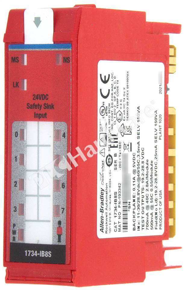
PLC Hardware Allen Bradley 1734IB8S Series B, Used in PLCH Packaging
1734 Oe2c Wiring Diagram

PLC Hardware Allen Bradley 1734IB8S Series B, New Surplus Open
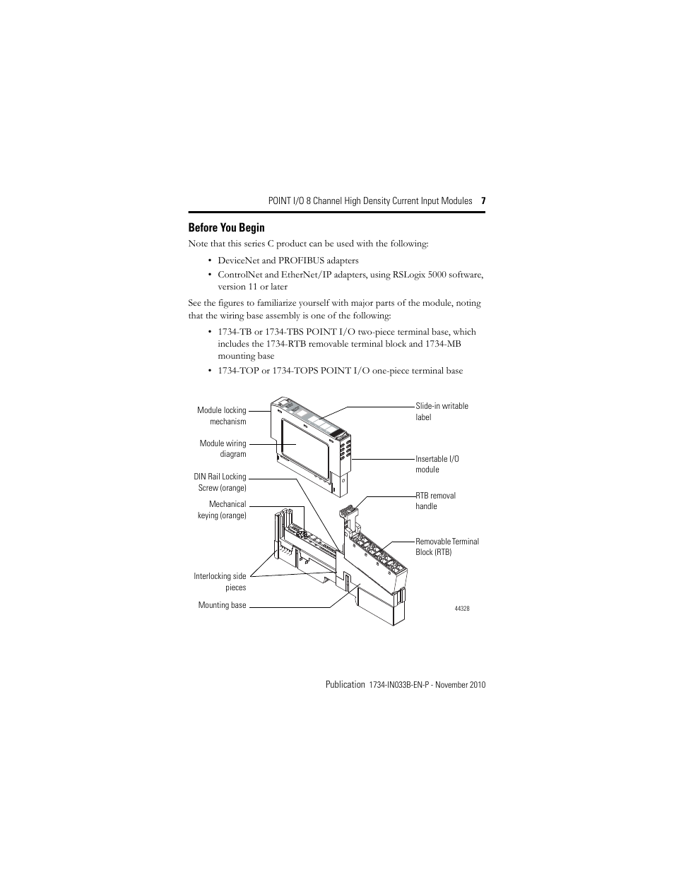
Before you begin Rockwell Automation 1734IE8C Installation Instructions User Manual Page 7 / 24
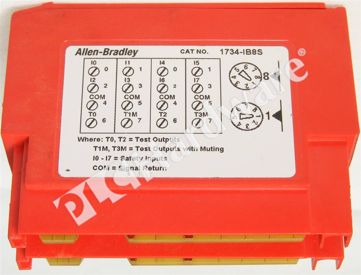
PLC Hardware Allen Bradley 1734IB8S Series B, Used in PLCH Packaging